IADR Abstract Archives
Quantify Torque Control During Retraction Using Implants: Finite Element Study
Objectives: Quantify Torque to develop strategic design of an appliance using Finite element method (FEM) for better and effective retraction of Maxillary anterior by using mini-implant anchorage with variable combination of force vectors
Methods: 3D model of Maxilla with associated structures converted into finite element model ANSYS(VER18) with 109821 nodes and 531302 elements on which study of different force vectors was conducted. Stainless steel, Brackets, Archwire and mini implants designed using Reverse engineering method. Force vectors from two levels of mini implants 13.5-mm HOT (high orthodontic traction), 8-mm LOT (low orthodontic traction) and two levels of anterior retraction hook (ARH), ARH1 5-mm and ARH2 8-mm and conventional molar hook.
Retraction force of 150gm/side with Coefficient of friction assumed to be 0.2
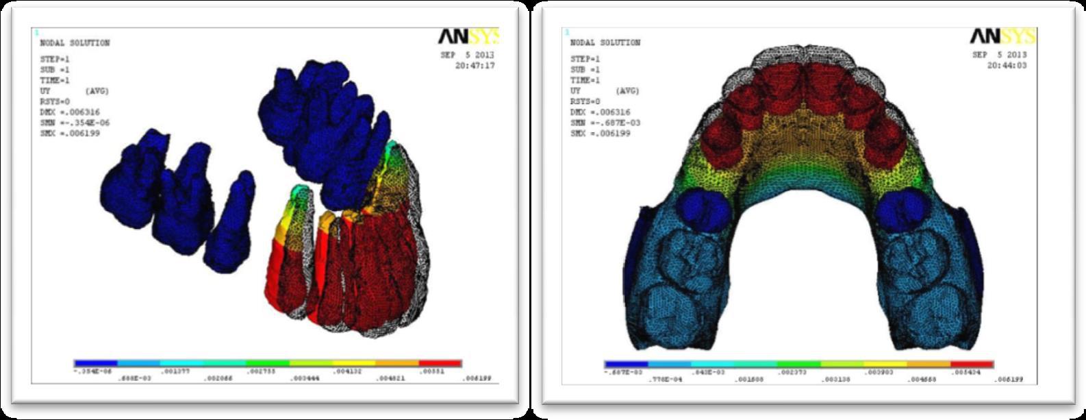
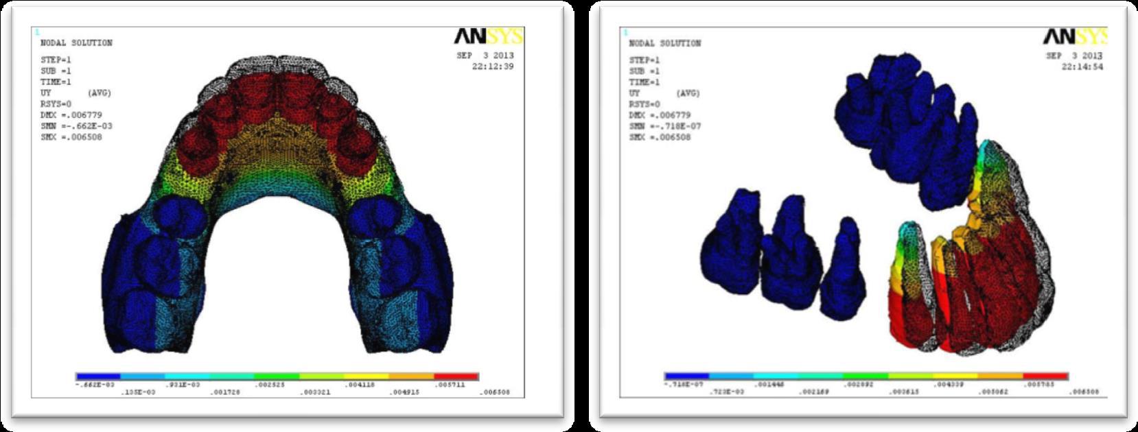
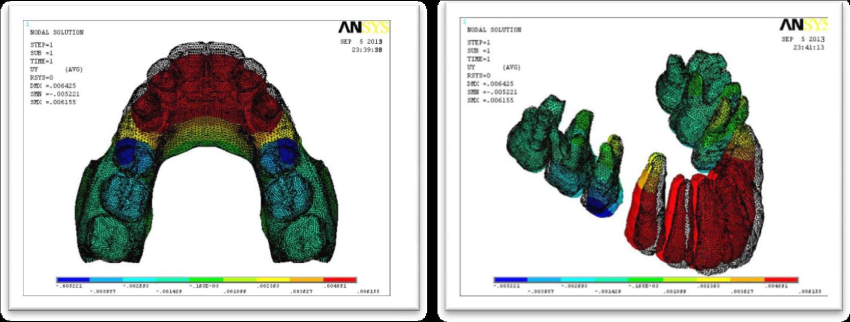
3D finite element analysis calculated deformation and represented in Y and Z axis.
1. Angle was measured between palatal plane and e long axis of maxillary central incisor, (PCI) was 110 degree before loading.
2. Linear perpendicular distance was measured from crown tip of maxillary central incisor to palatal plane (CIP), was 24.35mm before loading
Results:
HOT TO ARH1:- Mean displacement Y-axis 0.0058149 and Z-axis -0.0011645, PCI angle 109.943 and CIP 24.352mm
HOT TO ARH2:- Mean displacement Y-axis 0.0060477 and Z-axis -0.0018334, PCI angle 109.884 and CIP 24.367mm
LOT TO ARH1:- Mean displacement Y-axis 0.006529 and Z axis -0.001875 for crown tip ,PCI angle 109.856 and CIP 24.358mm
LOT TO ARH2:- Mean displacement Y-axis 0.006147 and Z-axis -0.001857,PCI angle 109.796 and CIP 24.392mm
MOLAR HOOK TO ARH1:-Mean displacement Y-axis 0.0057579 and Z-axis mean displacement -0.0017713, PCI angle 109.931 and CIP 24.392mm
Conclusions: Maximum torque loss observed in LOT to ARH1 model and minimum torque loss observed in HOT to ARH1 model. HOT to ARH1 model showed translation (most sought) else all the models showed controlled tipping


